project overview

The purpose of the circuit designed in this project was to help us understand NAND and NOR gates, common cathode descriptions and common anode descriptions, and how to wire a circuit of this type. This project had a few constraints; some of which includes 2-input gates, using at least one NOR or NAND gate, and completing the project in a timely fashion. This report will explain how the inputs (a-g) result in the outputs that form our date of birth.
truth table
The truth table is used to show the different midterm combinations that exist in order to provide the desirable output. Truth tables provide a numerical approach to viewing logic expressions. Once you have a truth table, you can come up with its equivalent circuit and simplified logic expression.
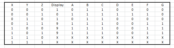
The "a" through "g" columns represent the seven parts of the seven segment display. They are the outputs in the circuit. In this project, we did not have to include dashes in our birth date. Therefore, we included "x's" instead. These "x's" represent "Don't Care Conditions". This means that it does not matter if the input is a one or a zero. We can manipulate the truth table (by choosing between zero and one) so that we can come up with the simplest logic expression. My logic expressions are shown below.
k maps and simplified logic for each of the seven segments
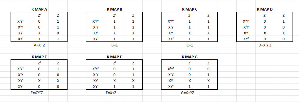
K-Mapping is a process in which you can create the simplest logic expression from a multitude of midterms. In order to come up with the simplest logic expression, you must start by creating a table with the outputs of the circuit. The table is built in a weird way. The individual midterms are placed on the top and left side of the truth table. They change as you go down and to the right. You can only change the inverted variables one at a time. You must place the outputs based on the midterms. Then, you would group all of the on outputs in the highest rectangle area that you can. You can then create one, simplified midterm from each rectangular area. The expressions are in Sums-Of-Product form. k-Mapping is faster than Boolean Algebra. It also decreases the likelihood of mistakes and human errors. I have so many expressions because there are seven segments that must be controlled in order for the circuit to work properly and create my specific birth date.
multisim
The image below is a picture of my Multisim circuit. I used the bus in order to minimize wires (and therefore confusion) and to make the circuit cleaner. The inputs are X, Y, and Z and the outputs are A, B, C, D, E, F, and G. I used the Common Cathode SSD instead of the Common Anode.
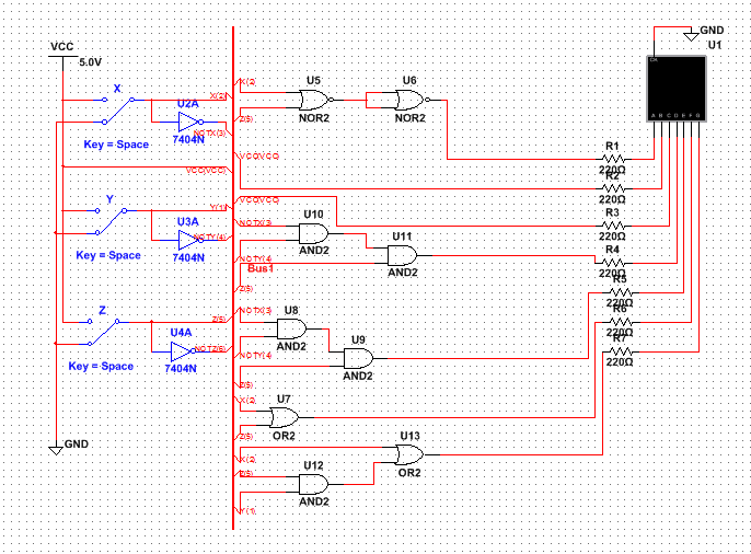
This circuit is in bus form. I used a total of 2 NOR gates, 3 AND gates, 2 inverters, and 2 OR gates. Given the number of gates, I would need 1 NOR chip, 1 AND chip (because a few midterms were the same), 1 inverter, and 1 OR chip. In this project, we were required to use one NAND or NOR gate in the circuit. I used a NOR gate in my circuit for Segment A because it used less gates than the NAND gates. I did not realize that the NOR chips are backwards compared to the other chips (and of course it is the only chip that is backwards and of course I picked that one). We use NAND or NOR gates because it may be a more effective and cost-efficient method of constructing a circuit. In my case, it was a more effective way to construct Segment A with a NOR chip than a NAND chip. I used 2 gates with the NOR chip, while the NAND chip would have used 3 gates. This is important because it can allow an engineer to save money and time when constructing their circuit.
The Seven Segment Display works through logic expressions. Each segment (A-G) has its own logic expression. Depending on the numerical value that you wish to display, the logic expression will reflect that. There are a few differences between the common cathode and the common anode. The common cathode must be connected to ground and in order to display a segment, the segment must be connected to power. It is just the complete opposite with common anode. The common anode must be connected to power. In order for a segment to be displayed, the segment must be connected to ground. We used the common cathode because it is easier to think of a "1" as being "on" and a "0" as being "off". If we used the common anode, the "1" would mean it is "off" and the "0" would mean that it is "on". The purpose of the resistor is to control the amount of current that flows into the Seven Segment Display.
The Seven Segment Display works through logic expressions. Each segment (A-G) has its own logic expression. Depending on the numerical value that you wish to display, the logic expression will reflect that. There are a few differences between the common cathode and the common anode. The common cathode must be connected to ground and in order to display a segment, the segment must be connected to power. It is just the complete opposite with common anode. The common anode must be connected to power. In order for a segment to be displayed, the segment must be connected to ground. We used the common cathode because it is easier to think of a "1" as being "on" and a "0" as being "off". If we used the common anode, the "1" would mean it is "off" and the "0" would mean that it is "on". The purpose of the resistor is to control the amount of current that flows into the Seven Segment Display.
bill of materials
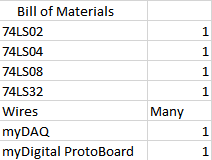
The bill of materials describes every piece of equipment that I used. I used one of each chip (AND, NOR, INVERTER, and OR). The myDAQ is the device that I used to test my circuit. The ProtoBoard is the breadboard that I used construct my circuit.
bread-boarding
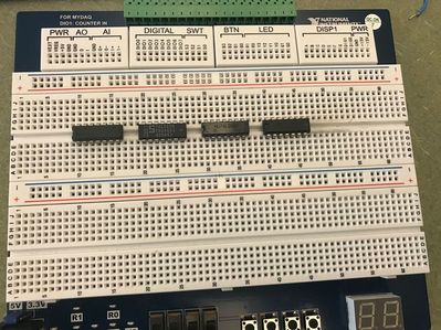
|
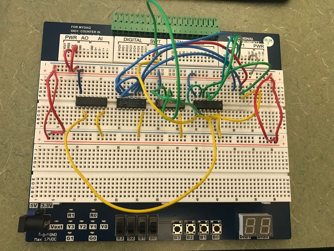
|
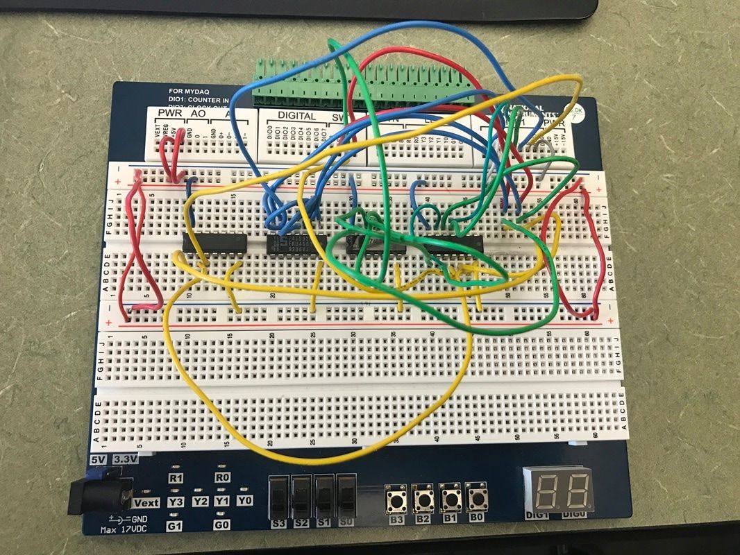
|
My second breadboarding experience was not as much fun as my first breadboarding experience. So no one bothered to tell me that the NOR chips ere backwards compared to the other chips. So I went and constructed this whole circuit, thinking that the NOR chips were going to be nice to me, and it did not work. Lovely. So I went and troubleshooted the circuit and I could not see a mistake. So what do you do when you do not see a mistake? Or take the whole thing apart and do it over, making sure you take your sweet, little time to do it. So I rewired it, and of course, it did not work. I rewired this whole thing about 4 times and even my (very smart) friends could not see where the problem lied. It was not until Mrs. Z got back that she told me that the NOR chips were backwards. And once I was given this lovely piece of information, the circuit worked. So I learned to always preserve and when it doubt, its probably backwards.
conclusion
This project taught me that sometimes it is okay to be backwards. On a more "school" note, I learned how to use a Seven Segment Display and how to wire a circuit to light it. Next time, I would make sure that I know in which direction the chips go. I would also take my time wiring so that I do not make any mistakes in the process. After this project, I would like to further study how a chip actually works and how an engineer goes about constructing it. K-mapping was very useful because it allowed me to create the simplified logic expression in one step. I love K-mapping because of its simplicity.
