project overview
The purpose of the circuit designed in this project and the project itself was to help us understand how to build a physical (working) circuit from the AOI design on Multisim and help us look for any mistakes. This report will explain the different combinations of how a majority can be carried out; in the end, the president is the most valuable vote. This project came with a few constraints and the hardest one was that we only had access to 2-input gates. (This did not make the project harder, some parts were just a bit more time consuming than others.)
problem concept
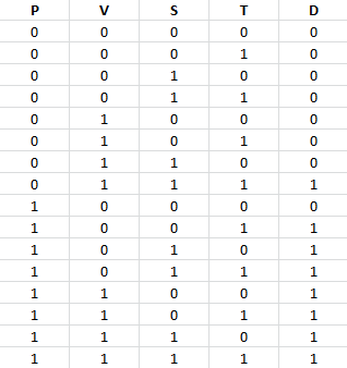
The purpose of the truth table is to numerically see which inputs can result in a positive (1) output. The "1's" represent a "yes" expression while the "0's" represent a "no" expression. In this situation, the event of a tie is broken by the president's vote. If there is a tie and the president's vote is "yes", then the output would also be a "yes" (and the same concept applies to when the president's vote is a "no"). The number of rows in the table is always equal to the number of variables raised in the exponent with a base of 2. In this case, there would be 16 possible outcomes because there are 4 variables and 2^4=16.
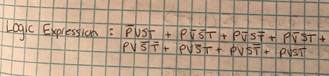
The un-simplified expression is seen below. It is in SOP (sum or products) form because it is the easiest form to derive from the truth table. Each midterm was found on the table. I located which products resulted in a 1 (vote passes) and put that into the expression. The line above the variable indicates that it is inverted; the variable is not on.
The un-simplified expression is seen below. It is in SOP (sum or products) form because it is the easiest form to derive from the truth table. Each midterm was found on the table. I located which products resulted in a 1 (vote passes) and put that into the expression. The line above the variable indicates that it is inverted; the variable is not on.
un-SIMPLIFIED circuit
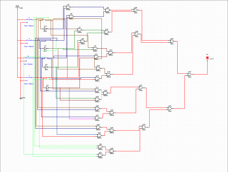
The circuit is very messy and complicated. There are a lot of wires and gates because this is the um-simplified circuit. It is also very messy because we only had access to 2-input gates. This circuit took me almost a whole class period to construct. It is not that the circuit was hard to build, but it was just very time-consuming and tedious to build. I used 4 inverters, 24 AND gates, and 7 OR gates. I also used a total of 6 74LS08 chips, 2 74LS32 chips, and 1 inverter.
boolean algebra
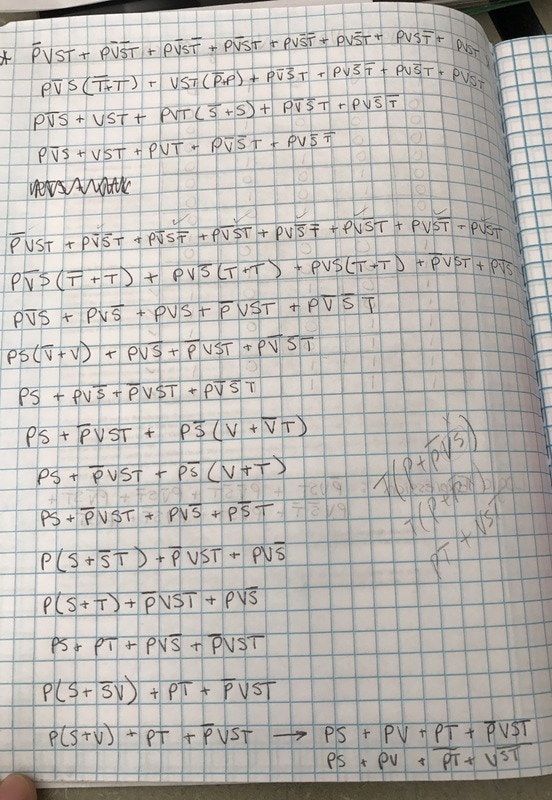
Boolean algebra is a mathmateical way to simplify circuit expressions. In this project, the simplified expression is PS + PV +PT + VST.
simplified circuit
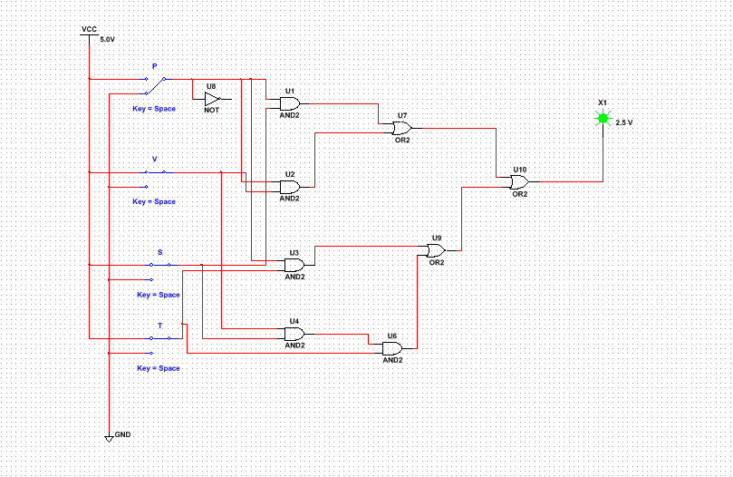
This simplified circuit is much more user-friendly, neat, clean, and understandable. Because there are less gates, chips, and wires, the circuit is simpler. Now, anybody who comes across this circuit can understand everything about it. The purpose of the resistor before the output LED is to join all of the midterms together. In this simplified circuit, I used a total of 5 AND gates, 3 OR gates, and no inverters (the inverter in the picture was there by mistake).I also used 2 74LS08 chips and 1 74LS32 chip.
The simplified circuit did contain fewer gates. It required 4 less inverters (the simplified version did not need any), 23 less gates, and 5 less inverters. This is very important because it saves materials, time, and money. If you were to build the un-simplified circuit rather than the simplified circuit, than you would spend more money and time making it. If you were to create the un-simplified circuit, than you would also have more chances of human errors. The simplified circuit is easier to understand and safer to construct.
The simplified circuit did contain fewer gates. It required 4 less inverters (the simplified version did not need any), 23 less gates, and 5 less inverters. This is very important because it saves materials, time, and money. If you were to build the un-simplified circuit rather than the simplified circuit, than you would spend more money and time making it. If you were to create the un-simplified circuit, than you would also have more chances of human errors. The simplified circuit is easier to understand and safer to construct.
bill of materials
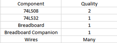
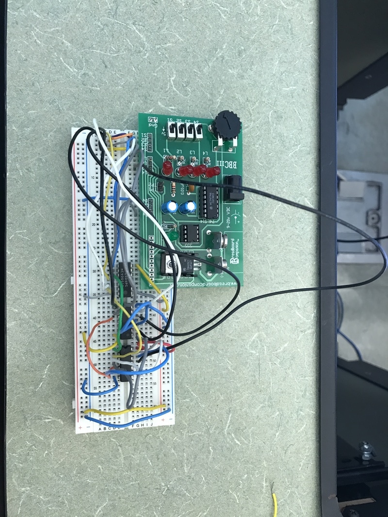
This table shows which materials I used for my circuit. In this project, we only had access to 2-input gates. Therefore, I used a total of 3 gates for the circuit. For my circuit, I needed one breadboard, one breadboard companion and a lot of wires.
|
|
|
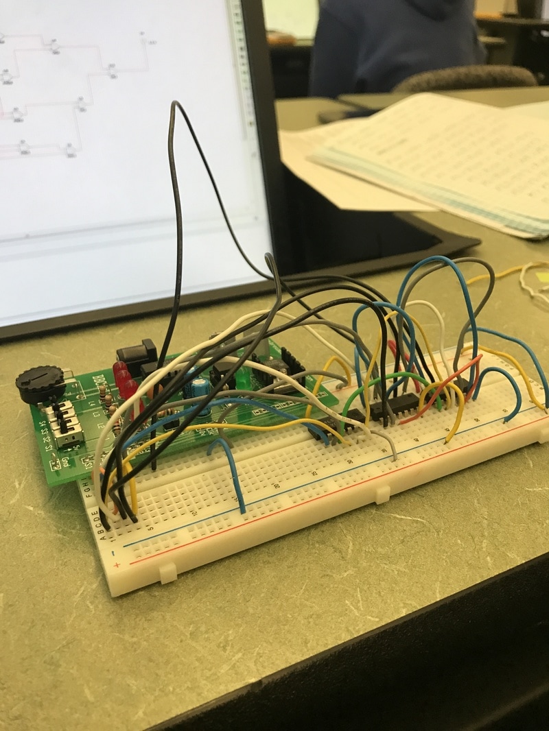
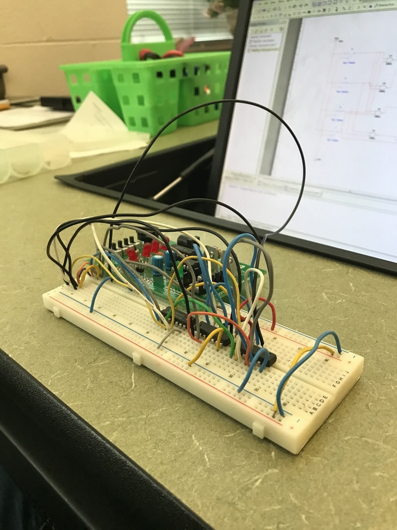
These pictures above show my circuit when it was completed. It took me a full class period to complete the breadboard circuit. There are a total of three gates used and many (many) wires. Luckily, the breadboard worked on the first attempt!
My first breadboarding experience was pretty fun. I had never breadboarded in my life before and I was really excited about starting this project. One part that I did have trouble with was when I had to multiply V x S x T. Because we only had access to 3-input gates, i had to multiply V x S first, and then multiply that output by T. I had to think about it for a second but it made sense afterward. Also, as I was wiring the breadboard, I noticed that one of my chips had a bent leg. Therefore, that leg was not inserted in the breadboard completely, and I exchanged it for another chip before I continued to wire. Because of this project, I also learned that taking things step by step is very important. I did not want to rush through the construction of the breadboard because I wanted it to work on my first attempt. I started out by focusing on the "pre-constrcution" aspects of the breadboard, like grounding all the chips, connecting the power sources, and ensuring that all of the components were functioning. Then, I focused on successfully completing each midterm. I did that until the breadboard was finished and it successfully worked. All in all, breadboarding was a fun experience!
My first breadboarding experience was pretty fun. I had never breadboarded in my life before and I was really excited about starting this project. One part that I did have trouble with was when I had to multiply V x S x T. Because we only had access to 3-input gates, i had to multiply V x S first, and then multiply that output by T. I had to think about it for a second but it made sense afterward. Also, as I was wiring the breadboard, I noticed that one of my chips had a bent leg. Therefore, that leg was not inserted in the breadboard completely, and I exchanged it for another chip before I continued to wire. Because of this project, I also learned that taking things step by step is very important. I did not want to rush through the construction of the breadboard because I wanted it to work on my first attempt. I started out by focusing on the "pre-constrcution" aspects of the breadboard, like grounding all the chips, connecting the power sources, and ensuring that all of the components were functioning. Then, I focused on successfully completing each midterm. I did that until the breadboard was finished and it successfully worked. All in all, breadboarding was a fun experience!
conclusion
This project consisted of some very important take-aways. One take-away is that troubleshooting is very important, not just in this project, but in every project that you do. Another take-away is that organization patterns can help you complete a project sooner. By organizing (and color-coding) the wires, it helps you locate any mistakes and keep your breadboard neat. This project shows that even the littlest detail can make a huge impact on the entire project. In Multisim, one wire that is not connected properly can cause the entire circuit to malfunction. In the breadboard, one mishap with the gates can prevent the circuit from working. When going from a problem statement to a finished circuit, you can start in many ways. First, you can construct a truth table (for reference). Next, you should construct and simplify the logic expression. Then, with the simplified expression, you can construct a virtual model on Multisim. Finally, you will have enough resources to construct the circuit on the breadboard. Boolean algebra is very useful when dealing with circuits. Boolean algebra allows the engineer to simplify their logic expression so that they are easier to work with and easier to understand. Boolean algebra is very useful when it comes to circuits.
