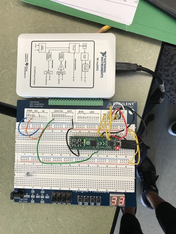
project overview

The goal of this project was to create a 4-bit asynchronous counter that would count from 0 to 80 and then suspend itself at 80. The operator would then have to press the reset button to initiate the counter again. The ones display would be controlled by an asynchronous counter designed with a 74LS93 MSI counter IC and the tens display would be controlled by D Flip-Flops. The project took about a week to complete. Everything was done on MultiSim and on the breadboard.
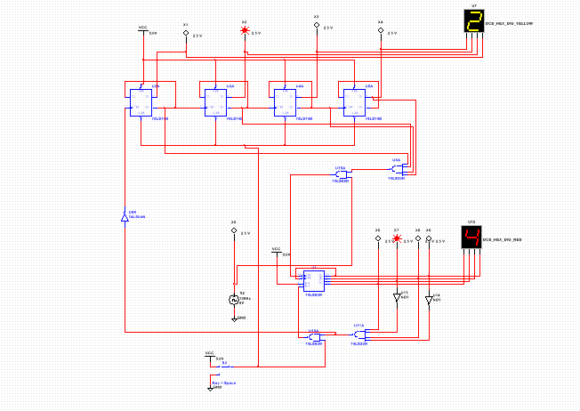
multisim circuit
pld circuit
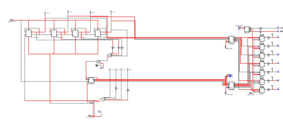
There are a few key differences between the PLD mode and design mode. In PLD mode, the circuit must have assigned pins. These pins can either be inputs or outputs. These pins have correlated spots on the CMOD chip. (If you put an input on Pin 4, you would connect that wire to pin 4 on the CMOD chip.) The CMOD chip helps you organize your circuit on the breadboard without the addition of too many wires. Also in PLD mode, you must upload your circuit to the CMOD chip. You have to export it to the chip from the PLD mode in order for the chip to function.
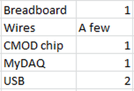
bill of materials
final project conclusions
SSI stands for Small Scale Integration while MSI stands for Medium Scale Integration. For SSI circuits, each chips only contains a few transistors. MSI circuits contain a lot more and therefore can make building a complex circuit easier. In this project, we used an MSI asynchronous counter. There are limitations to this type of counter. It always starts at zero and cannot be preset to another number. It also only counts up and never down. This is also a ripple counter. The meaning behind the term "ripple" comes from how the counter uses the clock. Only the first flip-flop is clocked by an external clock. All subsequent flip-flops are clocked by the output of the preceding flip-flop. Therefore, it forms a "ripple".
My circuit was slightly different than that of my classmates. Some had an extra gate here or there while others had one less. This goes to show that a circuit can be constructed in many different ways and still have the same output. The circuits were very similar, but they did not their differences.
When I push the push button, the clock initiates the sequence to begin. A signal travels to the input of the clock to start the count. Binary one is detected in the ones column and continues to count to binary nine. Once the ones place has reached binary nine, the tens column is initiated to begin counting from binary one to binary nine. The tens column will count from one to nine only when the ones column detects a nine. The tens column will suspend itself at eight because (it detects a nine) and the suspension is directly tied to the tens column. The reset switch resets both the ones and the tens column to zero and starts the count over again. Each a-g gate is connected to a pin that corresponds to a particular pin on the breadboard. I also pinned the clock and the reset switch on the breadboard.
