
hydrogen fuel cells
A hydrogen fuel cell is a power source that converts chemical energy (from a fuel source) into electricity. The electricity is produced when positively charged hydrogen ions react with oxygen (or another oxidizing substance). The first fuel cell was developed in 1839 by Sir William Grove. Once he had created the fuel cells, no other scientist/engineer furthered research on the subject. It was not until the 1930's when fuel cells were examined again. Francis Bacon took Grove's fuel cell, innovated it, and made it practical. He used Alkaline instead of Sulfuric Acid and used Nickel Powder. Bacon's fuel cell was less costly than Grove's was. Alkaline fuel cells have a higher voltage and use non-precious metals, which make it more eco-friendly. There are 6 different types of fuel cells: Alkaline, Polymer Electrolyte Membrane, Direct Methanol, Solid Oxide, Molten Carbonate, and Phosphoric.
solar panels
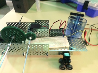
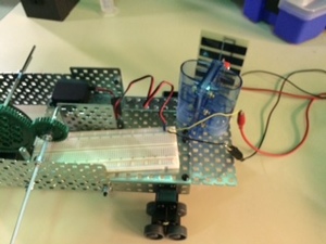
A solar panel is a device that absorbs light and stores it to produce energy. In most cases, solar panels absorb the sun's light and rays. Energy from solar panels is used to power homes, businesses, batteries and so much more. However, for this project, the light energy that we used was an artificial light. We did not rely on the sun because it is much easier and faster to build the fuel cell and power it inside. Plus, we would not have to rely on weather circumstances. In this project, the solar panel would be powered by the light, and that energy would be transfer to the fuel cell, which would transfer to the breadboard, and then would power the car motor.
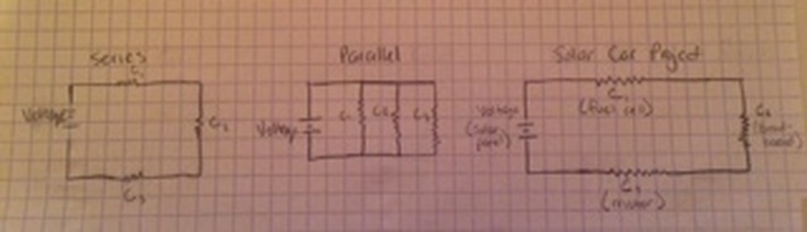
series and parallel circuits
There are two main types of circuits: series and parallel. In a series circuit, the components are connected end-to-end, and there is only one path for current to flow. Current flowing through every series component is equal, while the voltage flowing through every series component is different. The total resistance is equal to the sum of all the resistances of each of the components.
In a parallel circuit, the components are connected by both ends, which allows for many paths for current to flow through. Current flowing through every component is different, while the voltage flowing through every component is the same. The total resistance is equal to the reciprocal of the sum of the reciprocal.
In a parallel circuit, the components are connected by both ends, which allows for many paths for current to flow through. Current flowing through every component is different, while the voltage flowing through every component is the same. The total resistance is equal to the reciprocal of the sum of the reciprocal.
|
|
reflection
I liked learning about hydrogen fuel cells and electrical circuits. Knowing the difference between voltage, current and resistance is very important when constructing an electrical circuit and being able to apply those concepts is just as necessary. In order to have an efficient fuel source, you need to know the voltage, current, and resistance so your device can move and function at the needed speed. The easiest part of the project was constructing the fuel cell and the car. The fuel cell is easy to make, as long as you have the tools and the time to make it. The car took a little bit more thinking, but it was just a simple car that we were tasked to build. It had to have enough space to fit the breadboard, hydrogen fuel cell and solar panel.
The hardest part about this project was finding the electrical/energy measurements that were asked in the packet. Everyday, we would have to wait for the fuel cell to charge up before we could take any measurements. And every time, once the fuel cell was ready, it would be time to go. If we were able to charge the fuel cell earlier, it would have been easier to find and record our measurements.
The hardest part about this project was finding the electrical/energy measurements that were asked in the packet. Everyday, we would have to wait for the fuel cell to charge up before we could take any measurements. And every time, once the fuel cell was ready, it would be time to go. If we were able to charge the fuel cell earlier, it would have been easier to find and record our measurements.
activity 1.3.1
1. Read the Fuel Cell User Guide.
2. Follow the directions in the Fuel Cell User Guide under the section Preparing the Fuel Cell for Use.
3. Shine a bright light source on the solar panel, always keeping at least 8 inches of separation between the two to avoid melting the solar module plastic.
Set your multimeter to measure voltage and connect the multimeter test leads to the solar panel terminals. Move the solar panel or light source to determine the location that produces the highest voltage value. You may want to mark the positions with some tape. Record the open-circuit voltage. Note the current is zero, since a voltmeter has nearly infinite resistance.
VOC = Open-Circuit Voltage _1.51 Volts__ Power = VOC x 0 A = 0 W
4. With the test leads disconnected, set your multimeter to measure current. Return the solar module to the same exact position that produced the highest voltage value and measure the current. Record this short-circuit current. Note that the voltage is zero, since an ammeter has nearly zero resistance.
ISC = Short-Circuit Current ___0.0703 amps___ Power = 0 V x ISC = 0 W
5. Calculate the amount of power that would be produced by the solar module if it could simultaneously produce the voltage and current you measured in the previous two steps.
For this illumination level, the solar module will deliver, at most, about 70% of this theoretical maximum, and will do so at a resistance between zero and infinite resistance.
Maximum Theoretical Power = VOC x ISC = _0.106 watts___
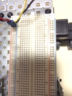
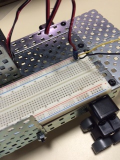
6. Attach the solar panel to the solar hydrogen automobile. Using a standoff or another suitable method, prop up one end of the chassis so that the motor-driven wheel is not in contact with the ground. Connect the motor leads to the solar module using the breadboard to make the connections. Position the light source to produce maximum voltage leaving a minimum distance of 8 inches between solar module and the lamp. Is there enough power to turn the motor? If so, is there enough power to turn the motor with the wheels on the ground? ___yes__
7. Set your multimeter to measure voltage. Connect the multimeter test leads to the solar module terminals. Record the load voltage value.(Drive gear should be engaged)
V = Load Voltage __________
8. Disconnect the test leads and set your multimeter to measure current. Connect the multimeter in series with the solar module. Record the load current.
I = Load Current = __________
9. Calculate the power delivered by the solar module when it is loaded by the motor with the wheels off the ground.
P = Load Power = I V = __________ for solar module.
10. Energize the fuel cell by using one of the power sources according to the directions in the Fuel Cell User Guide under the section Powering the Fuel Cell (Electrolysis).
Fuel cells can be damaged by high current. If using a DC power supply with the Heliocentris fuel cell, do not use more than 500 mA. Do not use a battery to energize the fuel cell.
11. After the fuel cell is energized, attach the fuel cell to the motor using the breadboard to make the connections. Is there enough power to turn the motor? If so, is there enough power to turn the motor with the wheels on the ground? ______
12. With the test leads disconnected, set the multimeter to measure voltage. Connect the multimeter test leads to the fuel cell terminals. Record the voltage value.
V = Load Voltage __________
13. With the test leads disconnected, set the multimeter to measure 10 A current, using the 10 A meter receptacle. Connect the test leads in series with the fuel cell.
Caution! Never measure current from the fuel cell without a resistor, motor, or other load in series with the ammeter. Doing so can permanently damage the fuel cell.
Record the current value. Load Current = __________
14. Calculate the power delivered by the fuel cell. P = Load Power = I V = __________ for fuel cell.
15. Remove the fuel cell and solar module and attach the two AAA battery holders to your vehicle using zip ties. Using the breadboard, connect the batteries in series with each other and with the motor. (See next step for wiring hints.) Is there enough power to turn the motor? If so, is there enough power to turn the motor with the wheels on the ground? ______
16. With the test leads disconnected, set the multimeter to measure voltage. Connect the multimeter test leads to the motor terminals. Record the voltage value.
V = Load Voltage __________
17. With the test leads disconnected, set the multimeter to measure 10 A current, using the 10 A meter receptacle. Connect the test leads in series with the motor terminals. Record the current value.
Load Current = __________
18. Calculate the power delivered by the batteries in series. P = Load Power = I V = __________ for batteries in series
19. Using the breadboard, connect the batteries in parallel with each other and with the motor. Is there enough power to turn the motor? If so, is there enough power to turn the motor with the wheels on the ground? ______
20. With the test leads disconnected, set the multimeter to measure voltage. Connect the multimeter test leads to the motor terminals. Record the voltage value.
V = Load Voltage __________
21. With the test leads disconnected, set the multimeter to measure 10 A current, using the 10 A meter receptacle. Connect the test leads in series with the motor terminals. Record the current value.
Load Current = __________
22. Calculate the power delivered by the batteries in parallel.
P = Load Power = I V = __________ for batteries in parallel
2. Follow the directions in the Fuel Cell User Guide under the section Preparing the Fuel Cell for Use.
3. Shine a bright light source on the solar panel, always keeping at least 8 inches of separation between the two to avoid melting the solar module plastic.
Set your multimeter to measure voltage and connect the multimeter test leads to the solar panel terminals. Move the solar panel or light source to determine the location that produces the highest voltage value. You may want to mark the positions with some tape. Record the open-circuit voltage. Note the current is zero, since a voltmeter has nearly infinite resistance.
VOC = Open-Circuit Voltage _1.51 Volts__ Power = VOC x 0 A = 0 W
4. With the test leads disconnected, set your multimeter to measure current. Return the solar module to the same exact position that produced the highest voltage value and measure the current. Record this short-circuit current. Note that the voltage is zero, since an ammeter has nearly zero resistance.
ISC = Short-Circuit Current ___0.0703 amps___ Power = 0 V x ISC = 0 W
5. Calculate the amount of power that would be produced by the solar module if it could simultaneously produce the voltage and current you measured in the previous two steps.
For this illumination level, the solar module will deliver, at most, about 70% of this theoretical maximum, and will do so at a resistance between zero and infinite resistance.
Maximum Theoretical Power = VOC x ISC = _0.106 watts___
6. Attach the solar panel to the solar hydrogen automobile. Using a standoff or another suitable method, prop up one end of the chassis so that the motor-driven wheel is not in contact with the ground. Connect the motor leads to the solar module using the breadboard to make the connections. Position the light source to produce maximum voltage leaving a minimum distance of 8 inches between solar module and the lamp. Is there enough power to turn the motor? If so, is there enough power to turn the motor with the wheels on the ground? ___yes__
7. Set your multimeter to measure voltage. Connect the multimeter test leads to the solar module terminals. Record the load voltage value.(Drive gear should be engaged)
V = Load Voltage __________
8. Disconnect the test leads and set your multimeter to measure current. Connect the multimeter in series with the solar module. Record the load current.
I = Load Current = __________
9. Calculate the power delivered by the solar module when it is loaded by the motor with the wheels off the ground.
P = Load Power = I V = __________ for solar module.
10. Energize the fuel cell by using one of the power sources according to the directions in the Fuel Cell User Guide under the section Powering the Fuel Cell (Electrolysis).
Fuel cells can be damaged by high current. If using a DC power supply with the Heliocentris fuel cell, do not use more than 500 mA. Do not use a battery to energize the fuel cell.
11. After the fuel cell is energized, attach the fuel cell to the motor using the breadboard to make the connections. Is there enough power to turn the motor? If so, is there enough power to turn the motor with the wheels on the ground? ______
12. With the test leads disconnected, set the multimeter to measure voltage. Connect the multimeter test leads to the fuel cell terminals. Record the voltage value.
V = Load Voltage __________
13. With the test leads disconnected, set the multimeter to measure 10 A current, using the 10 A meter receptacle. Connect the test leads in series with the fuel cell.
Caution! Never measure current from the fuel cell without a resistor, motor, or other load in series with the ammeter. Doing so can permanently damage the fuel cell.
Record the current value. Load Current = __________
14. Calculate the power delivered by the fuel cell. P = Load Power = I V = __________ for fuel cell.
15. Remove the fuel cell and solar module and attach the two AAA battery holders to your vehicle using zip ties. Using the breadboard, connect the batteries in series with each other and with the motor. (See next step for wiring hints.) Is there enough power to turn the motor? If so, is there enough power to turn the motor with the wheels on the ground? ______
16. With the test leads disconnected, set the multimeter to measure voltage. Connect the multimeter test leads to the motor terminals. Record the voltage value.
V = Load Voltage __________
17. With the test leads disconnected, set the multimeter to measure 10 A current, using the 10 A meter receptacle. Connect the test leads in series with the motor terminals. Record the current value.
Load Current = __________
18. Calculate the power delivered by the batteries in series. P = Load Power = I V = __________ for batteries in series
19. Using the breadboard, connect the batteries in parallel with each other and with the motor. Is there enough power to turn the motor? If so, is there enough power to turn the motor with the wheels on the ground? ______
20. With the test leads disconnected, set the multimeter to measure voltage. Connect the multimeter test leads to the motor terminals. Record the voltage value.
V = Load Voltage __________
21. With the test leads disconnected, set the multimeter to measure 10 A current, using the 10 A meter receptacle. Connect the test leads in series with the motor terminals. Record the current value.
Load Current = __________
22. Calculate the power delivered by the batteries in parallel.
P = Load Power = I V = __________ for batteries in parallel
conclusion questions
1. Using the measurements you made, compare and relate the four options you explored. Was the car best powered by a single fuel cell, a single solar module, two AAA batteries in series, or two AAA batteries in parallel?
Due to lack of time, my team and I were not able to complete the four options of power. But through some inferencing and research, I was able to come up with a theory. I believe that using two AAA batteries in a series circuit would power the car best. The AAA batteries would be much more efficient in a series circuit rather than a parallel circuit because there is only one path for the energy to flow. In a parallel circuit, there are many paths for energy to flow, which can cause less energy to get to the motor. And when comparing the battery to a solar panel and the solar module, the solar panel and module would only work if it was sunny outside. If it was not, it would not produce the most energy and power.
http://www.solarpowerworldonline.com/2013/05/what-are-solar-panels-made-of/
http://www.forbes.com/sites/williampentland/2013/06/12/self-charging-solar-cells-better-than-batteries/
2. Did voltage, current, or power best describe the suitability of a power source?
Power described the suitability of the power source better than voltage or current. Voltage is the pressure that causes current to flow and current is the actual flow. Power is the amount of work that was actually used for the desired purpose.
3. If you had many solar modules, how many of them would be needed to get the same performance from the car as the performance observed with two AAA batteries? Describe or sketch how would you connect the solar modules in terms of parallel and series circuits.
Again, due to lack of time, my group and I were not able to test the solar modules and AAA batteries. However, I know that (based off of my calculations) the maximum power the the solar module would produce is 0.0742 watts. (My maximum theoretical power is 0.106. At most, the solar module would deliver 70% of the theoretical power, which is 0.0742 watts.) Once site said that one AAA battery produces a little less than 2 watts. So depending on exactly how much power two AAA batteries can produce, we can figure out how many solar modules would be needed. (Based on this information, it would take about twenty-six to twenty-seven solar modules.) I would connect the solar modules in a series circuit because it would produce more energy than in a parallel circuit.
http://www.doityourself.com/stry/how-many-watts-are-in-aaa-batteries#b
4. If you had many fuel cells, how many of them would be needed to get the same performance from the car as the performance observed with two AAA batteries? Describe or sketch how would you connect the fuel cells in terms of parallel and series circuits.
Again, due to the time constraints, my group and I were not able to measure the power for the fuel cells. But based on some research, I predict that it would take about 13 fuel cells. Each fuel cell produces about .16 watts of power. I would connect them into a series circuit because that would produce more power than a parallel circuit would.
https://intraweb.stockton.edu/eyos/page.cfm?siteID=82&pageID=24
5. Describe and defend a system that you believe would best utilize a solar hydrogen system to meet the needs for an average driver.
In order to best utilize a solar hydrogen system, you would need to a) put it in a place where it would receive the most sunlight and b) in a position where the distilled water would not fall out. The fuel cell itself should be protected with an outer layer so that the distilled water will not fall out. The fuel cell could be redesigned so that it has an outer layer attached to it. As for the solar panel, the device should be placed where it will get the most sunlight possible. The panel should be placed on the roof of the car. The roof of the car is where it will be exposed to the most sunlight possible. In order to make this system super successful, I think that the solar panel should be placed on the roof of the car, and the fuel cell should be placed inside the car (like actually in the car!).The solar panel would connect to the fuel cell easily, and there would be little room for the distilled water to fall out. If the fuel cell was inside the car, then it would be easier for the engine to connect to it.
6. How does a photovoltaic cell work? Record the source of your information.
A photovoltaic cell is pretty much the same as a solar cell. It captures light and turns it into usable energy. A photovoltaic cell consists of 2 layers : one positive and one negative semi-conductive layers. Particles of solar energy, called photons, reflect, pass through, or are absorbed by the cell. When the negative layer has collected enough photons, the layer frees electrons. These electrons naturally move to the positive layer. The movement of these particles cause energy. This energy is similar to the energy in a household battery.
http://solarenergy.net/solar-power-resources/how-photovoltaic-cells-work/
7. Detail how electrolysis separates hydrogen and oxygen. How is electricity produced as the fuel cell allows the hydrogen to reunite in a bond with oxygen? Record the source of your information.
Water molecules are created when one negative oxygen atom connects to two positive hydrogen atoms. Electrolysis is the process in which the hydrogen and oxygen molecules are split up. In order to do this, an electric current is needed. When electricity is produced through a molecule, an anode (positive) and a cathode (negative) ion will attach to the oppositely charged atom. The anode will attach itself to the oxygen atom and the cathode will attach itself to the hydrogen atoms. Depending on their ionic charge, the atoms will lose or gain electrons in order to become electrically stable (oxygen will loses, hydrogen will gain). As the fuel cell allows the hydrogen to reunite in a bond with oxygen, electricity is produced when the atoms knock out an electron. Oxygen and hydrogen will kick out any electrons that are not needed. The process of moving electrons creates electricity.
http://socratic.org/questions/how-dpes-electrolysis-separate-hydrogen-and-oxygen
http://www.instructables.com/id/Separate-Hydrogen-and-Oxygen-from-Water-Through-El/
