explanation
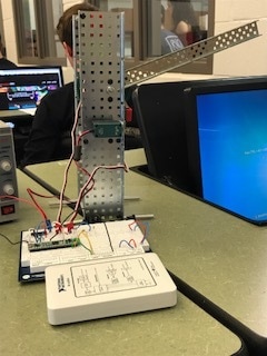
In this project, we were tasked to build a toll booth. The gate would be closed at the beginning of the simulation. When a button is pressed, the gate would open because the limit switch would cause it to. Once the gate opens fully, another limit switch would be hit and that would cause the gate to close. The motors cause the lever to move up and down. This entire simulation is programmed through Multisim and the CMOD chip.
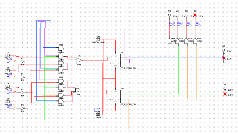
The input variables are Open Switch Pushbutton, Closed Switch Pushbutton, Open Limit Switch, and Closed Limit Switch. Each of these variables, when activated, cause the toll booth to move. The output variables are the Motor Close, Motor Open, Gate Close, and Gate Open. We used these variables to program multisim. The Open Switch causes the motor to open. The Open Limit causes the gate to open. The Closed Switch cases the Motor to close and the Closed Limit causes the gate to open.
Each output is based on the present state. In this case, the present states are represented by QA and QB. Based on what state is active, the toll booth will act accordingly.
multisim
vex
conclusion
Our design process began with the packet that was given to us. There were many moving parts and ideas so we immediately started working on the transition table, state graph, and boolean algebra simplification of the equations needed for the mulitsim implementation. It was a little tough getting started; we did not know exactly where to start but together we got the ball rolling. One mistake we made was that we forgot about little details. We over complicated a few parts and it took us longer to complete these sections of the project than we had liked. Nonetheless, the project was completed on time and well. This project was similar to the other projects that we did because of our multisim implementation and the use of the CMOD chip. This project was very similar to the copy jam project because it required out of the box thinking and it used a real life situation. This project was different from some of our other ones because it required the advanced knowledge of transition tables, state graph, and state machines overall. While doing this project, I learned the schematics are really exactly what they show. It was hard to understand them at first but looking them over helped smooth out the rough edges. I feel that it was easier at the beginning of the year because our units were simpler and therefore the schematics were simpler. Next time, I would research how to properly read a schematic so I know that I am doing it correctly and accurately.
